This is a wide subject, and to be properly and thoroughly dealt with requires much more space than has been placed at my disposal, so that I shall simply endeavour to deal broadly with the principles of the best known types. Next to the engine itself the construction of the transmission gear is the most important thing about an autocar; for as this portion of the machine is the medium through which the power is conveyed from the engine to the wheels, it does not require an intimate knowledge of mechanics to perceive that bad design and undue friction here may make a very material difference in the running and speed of the car. As a matter of fact the whole power of the engine is never available for the work of turning the wheels of the car, a certain portion of it always being absorbed in the work of driving the gear; indeed, it is not too much to say that in some instances—as has indeed been proved by actual tests—fully one half of the power developed by the engine is thus lost between the motor and the wheels. Consequently high efficiency in the transmission arrangements will mean greater economy in work, as well as better hill-climbing and speed results from the same engine, than would have been the case had a more faulty system been adopted. Broadly speaking, it may be said that the old adage 'simplicity is a virtue' holds particularly good in this connection, and it may be taken as an axiom that—all other things being equal—the simpler the gear the better and more efficient will it be.
That being so, it may not unnaturally be asked why the simplest method is not always used. If it were only the matter of conveyance of the power from the motor to the road wheels, doubtless this would be done; but where the petrol or internal combustion motor is used another matter has to be provided for, and that is the variation of the ratio of engine speed to wheel speed; for with the great majority of motors of this type, unless the speed rate of the motor can be maintained, it will stop, so that 'variable gearing' has to be adopted and the power sent through this to the wheels. By this I mean that the means of transmission may be so altered at will that whereas when on level ground the engine may make, say, only two revolutions to each one of the road wheels, for hilly or heavy work it may make, say, four, six, or eight, and so, whilst the car travels slower, the engine speed may remain the same. Where steam engines are used this is not usually required, as the steam engine obtains more power for heavier work by the use of more steam.
Now the simplest method possible would be the driving of the road wheels or wheel direct by the piston-rods of the engine, a plan only possible where a very small wheel is used, and only actually employed in the Holden bicycle as described in the chapter devoted to this type of machine. Next to this comes the use of gear wheels—'cog' wheels—as employed upon tricycles and some light forms of car where the motor is set close to the axle. In these we have one gear wheel fixed to the shaft of the motor, gearing into a similar one upon the axle. And here we may halt for a moment to consider the action of gear wheels. As will be seen by fig. 1, we have two wheels, the edges of which are cut into a number of equal-sized teeth, and these wheels are so fixed in relation to each other that the two sets of teeth mesh or interlock with each other. Now it will be seen that any movement of one will be imparted to the other through the teeth, but in an oppositedirection thus if wheel a revolves to the right, wheel b will turn to the left, and vice versa. There is also another peculiarity about these wheels. It will be noticed that they are of different sizes. The result is that if wheel a is the first to receive the power, one turn of the wheel will not cause wheel b to make a complete turn, whilst, conversely, wheel b being the larger of the two, will, if revolved, cause wheel a to turn more than once. Just what their actual relation of movement to each other may be, is determined actually by their respective diameters and, for ease of calculation, by the number of teeth they respectively contain. Thus if wheel a contains 20 teeth and wheel b 50, it will take 21/2 turns of a to revolve b once,
Fig 1.
whilst one revolution of b as the driver would cause a to go round 21/2 times. It will thus be seen that by varying the size of the different gear wheels used, the ratio between engine and road wheels can be varied. In an arrangement employing this simple form of transmission only, the engine and axle must be set close together, and we only have the friction in the bearings of the engine and road wheels to be overcome, together with that caused by the teeth of the gear wheels as they engage with and push each other around. When, however, it is found desirable that the engine should be separated from the road wheels, some other form of transmission becomes necessary, and other means have to be adopted; and the simplest and cheapest in point of manufacture, though not the most efficient, is shown in fig. 2, where we have, as before, two different-sized wheels, one connected with the motor-shaft and the other with the driving-axle of the road wheels. Instead, however, of their faces or edges being cut into teeth, they are smooth, and the two are connected by a flat leather belt. Here, as before, the wheels will be revolved in relation to each other according to their respective diameters, but, as shown by the arrows, they will both revolve the same way. This is advantageous, for every time the direction of power application is changed some loss takes place. By crossing the belt, however, the pulleys or belt wheels may, if desired, be made to revolve in opposite directions. On the other hand, the
Fig. 2
connection, not being positive, but depending upon the tightness or grip of the belt, there is more or less slip, so that the ratio of rotation is not constantly the same, and as, in order to obtain sufficient grip for heavy work, the belt has to be tightly stretched, the two wheels at either end are forcibly pulled towards each other, and some extra friction, through pressure, produced in the bearings. The slip of the belt, however, is not altogether a disadvantage, as it absorbs the shock of the engine and prevents damage from that cause, whilst there being no metallic parts in contact, belt driving is quite silent in running, and this cannot be said of gearing, much of which is very noisy, which is not only an annoyance but an eventual source of trouble, as noise means wear.
Another form of transmission may be said to combine the principal features of both the previous systems, and that is chain driving. Here, as before (see fig. 3), we have two wheels or pulleys connected by a flexible band, but the pulleys are not smooth as before. Their faces are cut into teeth suitably shaped to engage the links of a metallic chain which takes the place of the belt. As with belt driving the driven pulley or chain wheel, b, revolves in the same direction as the driving pulley or sprocket a. This method possesses the feature of positive driving belonging to the gear wheels, and whilst it has none of the slip of the belt there is some elasticity in the chain, which helps to take up driving
Fig. 3
shocks and secures silent running. The extra friction on the bearings necessitated by belt driving is avoided, as the chain may be run fairly slack and the lower side hang loosely as shown in the diagram, the chain automatically tightening itself at the top as the different links are taken up by the teeth in the drive.
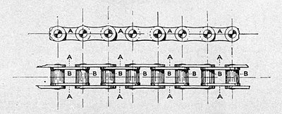
Where two chains are used there is frequently some rattle, owing to the two not being able to run exactly together, but a single chain is—like that of a bicycle, which it much resembles— practically silent. Wet, mud, and dust will also cause chains to 'grind' and become noisy, and therefore in order to obtain the best results they should be enclosed in a cover or gear-case, which will protect them from these enemies; and the same may be said of both gearing and belts, for both are better servants in every way if so protected. The chains used are similar in construction to those fitted upon bicycles, and are either of the 'block' or 'roller' variety. In the former (see fig. 4) the side links, c, c, c, are connected by solid blocks of
Fig. 4
metal, a, a, a, through the ends of which the connecting pins, b, b, b, pass, these pins turning slightly in their bearings in the blocks as they pass round the chain wheels. In the latter shown in fig. 5 the blocks are replaced by connecting plates a, a, a, and upon the cylindrical separators connecting them
Fig. 5
small cylinders or rollers, b, b, b, are fitted, which roll into and out of the chain-wheel teeth as they come round. As a rule, unless some special provision is made for thorough lubrication of the connecting pins of the blocks, roller chains are usually found to run with the greater smoothness and quietude. In addition to these methods we have yet another which has been very largely used lately, especially upon light cars, and that is the use of bevel gearing and a connecting-rod, with universal joint to secure flexibility. This system is shown in figs. 6, 7,
Fig. 6
Fig. 7
8 and 9. Here we have a rod or shaft with a gear wheel at
Fig 8.
one end. This wheel, however, is conical or bevelled (see a, figs. 6 and 7), and the teeth are wider on the outside than upon the inside. It engages with a wheel b upon the axle or other portion of the machinery, which is also bevelled, and bears corresponding teeth. It will be seen that whereas in each of the three methods first described the axes of the motor shaft and wheel axle are parallel, in this case they are at right angles, the forward end of the shaft being united to the motor shaft by a clutch or other suitable means, and rotated by it. In action these bevelled wheels are similar to the gear wheels first described, but instead of revolving lightly on their bearings and pushing round the teeth of the opposite wheel as they come in contact, their shape causes a strong repelling action also to take place, the tendency of the bevelled faces of the gear wheels being to force themselves apart, which throws a considerable cross strain upon the bearings. The power, too, is deflected at right angles, which is another source of loss.
In order to permit of the free vertical movement of the wheels under the springs, two universal or 'Cardan' joints, c, c, are fitted within the length of the shaft d (see fig. 8). These consist of two jaws set at right angles, with their ends connected to and rocking upon the extremities of a right-angled connecting piece. This allows movement in all directions and the shaft accommodates itself to the conditions of the drive. This method is chiefly used because of convenience and some neatness.
Another plan, employed however only by one or two firms, substitutes for the bevel gearing what is known as skew or screw gearing, a very smooth and silent drive without the spreading or bursting action of the bevels, the end of the driving shaft being fitted with a screw which drives a series of teeth cut diagonally around the circumference of the driven wheel.
I have said above that the forward end of the arbor shaft is connected to the engine shaft by a clutch, and this brings me to another almost universal and very important portion of the transmission gear. In belt-driven cars a clutch is rarely used, the slip of the belt being relied on to give the necessary immunity from shock, but in cars which are driven by chains, arbor shaft, or gearing, a clutch is a necessity, otherwise the sudden application of power would strip the teeth of the gear, break the chain, or cause other damage, and something is needed to ease the shock. Clutches may be 'positive' or frictional, but friction clutches only are referred to above. These commonly take the form of a truncated cone or inclined surface so arranged upon that portion of the transmission which carries the gearing or other connection with the wheels that, by sliding it slightly forward, it enters a socket having an internally coned surface into which it exactly fits. Sometimes one of the surfaces is covered with leather, but otherwise both are metallic, and a strong spring is usually fitted at the back of the cone by which it is forced into its socket. In a great many of the most popular types of car the hollowed socket for the cone is formed in the centre of the fly-wheel of the engine, which thus drives the mechanism through the clutch. The spring has a certain tension, and the friction between the two surfaces when pressed together by the spring is sufficient to drive the car without slip under all ordinary circumstances; but at starting, when the power is applied suddenly to an inert mass, a much greater amount of friction is engendered, and the cone slips slightly in
Fig. 9
its socket, thus saving the gearing and the machinery from jar and shock, and enabling the power to be applied gently. The construction of a clutch of this character is shown at fig. 9.
Occasionally also two friction clutches acting in opposite directions are used to connect or disconnect alternately some portion of the gear, in which case they are not spring held, but are moved from side to side by a lever—thus, in fig. 10 we have two gear wheels, which may be of different sizes, running on one shaft with a double clutch between them. By moving the clutch over to the left, wheel a is held fast to and driven by the shaft upon which the clutch slides, whilst by moving it in the opposite direction, wheel a is freed, and wheel b held fast, and if the clutch be held stationary at a point midway between the two, both wheels are free and neither is driven. In another form of clutch, connection is made by expanding friction rings on the inner faces of drums, fixed to the parts to be driven. Positive clutches are used temporarily to connect various portions of the gear from time to time, as may be required, and these take the form of notches or projections upon a sliding ring or collar or other part of the machinery which, when moved along a shaft, can engage with or slip into
Fig. 10
corresponding notches or projections on the part with which it is desired to make connection. In this case the connection is sudden, and from a position of absolute rest the part put into gear by the clutch is instantly moved forward at the same velocity as the rest of the machinery the moment the clutch teeth slip into their places. Figs, 11, 12, and 13 show a common form of positive clutch. This form of clutch, it may be noted, is—or should be—always used in conjunction with a clutch of the friction order—i.e. whilst individual portions of gear may be connected with and disconnected from each other by the use of positive clutches, a friction clutch always connects the engine with the machinery so that the shock is taken up there. The teeth, notches, or projections of positive clutches require to be very carefully and accurately cut and properly hardened, for if they are not they are very apt to be chipped and to wear by the action of engagement.
Fig. 11
Rough edges denote chipping, and rounded edges much out ot shape indicate wear. When this is the case the gear becomes very noisy in action, and much movement of the parts is noticeable when the actuating lever is moved to and fro. In these circumstances they will require facing or re-cutting, and this should be done at once when such a condition of things is discovered,
Fig. 12.—SectionFig. 13—End Section
or the condition of the parts will rapidly go from bad to worse. These latter remarks also apply to the teeth of gear wheels.
Having now briefly considered the principal details of simple transmission, we pass on to the means whereby the ratio of the gears may be altered as required by the road conditions, and in so doing have to combine the speed-varying gear with the transmission gear proper; and the best way to do this perhaps will be to illustrate the principles employed by reference to examples of the various systems.
In the first place, belt-driving cars have usually two belts running on pulleys of different sizes, so that shifting the belts causes either one or the other of the two speed ratios to be used. The belt system generally drives the car through chains, so that whilst belt gearing is used for the speed variation, the transmission to the wheels is by chains.
In using belts care must be taken in shifting the belts to throw off one before attempting to put the other into operation, or broken belts and perhaps worse accidents may result. Belt driving is wonderfully smooth and quiet in action, and commendable from this point, but unless very carefully looked after liable to give trouble by undue slipping and breaking. When carefully attended to and intelligently applied, belts can be made very satisfactory. Mr. Lyons Sampson, for instance, tells me he has had one pair of belts in use for over a year, and has had no trouble with them. But then Mr. Sampson has given the subject very careful consideration, and sees that they get the little care they need. For instance, he runs his belts flat instead of crossed, which by not bending them so much puts less strain on the fibres. He uses the belt, too, with the skin side to the pulleys, protects them as much as possible from wet, and uses loose pulleys of the same diameter as the fast ones instead of slightly smaller, as is usual. This, whilst keeping the strain on during use, does not necessitate the belt being pushed up over the sharp edge of the fast pulley every time it is put into action. Mr. Sampson is also careful to take the belts off entirely when the car is not in use, and so relieve them of strain.
Mr. R. W. Buttemer, another successful belt-user, recommends using lightly tanned leather for the belts instead of raw hide, which is preferred by some, and before putting on a new belt hangs a 1-cwt. weight on it for a day or two to take the stretch out of it, following this by a soaking in castor oil, which oil is also occasionally applied during use. The wider and longer the belt, the larger the pulleys, and the faster their speed of rotation the better will the results be, so that narrow or short belts and small pulleys in positions of no great speed should be avoided. If a belt slips unduly its under surface may be treated with Sternoline belt dressing, which very much increases the grip, and Mr. Buttemer has a good word to say for Collan oil for this purpose; but if this is not effective, it is evident the belt has stretched, and it must be taken off, half an inch or more, as required, cut off one end, and the two ends joined up again with a belt fastener, which consists of a small malleable iron casting carrying rows of teeth which are driven into the belt with a hammer. Failure of these to hold is generally due to their having been flattened out by hammering. In joining up a belt see that it is cut square across and the two parts joined in accurate alignment. The belt may also be joined by lacing the two ends together with a strong leather lace, a method which Mr. Buttemer advocates when using new unstretched belts, as then the stretch may be taken up by tightening the lacing without taking off the belt again. 'The secret of success with belt driving,' writes that gentleman, 'is to have belts as large as admissible, of sufficient substance and good leather, protected from wet and mud and well dressed with castor or Collan oil, and under these conditions they should never give trouble beyond the occasional taking up of slack.'
The usual arrangement provides two speeds only, and to get a third speed for surmounting excessive gradients the loose pulley of the lower gear is furnished with what is termed a 'Crypto' gear which, however, is not a true Crypto, but what is known as a lathe back-gear action, fitted to a revolving drum, the holding of which by a brake tightened around its surface and put into operation by a handle causes the gear to come into action, and so effect a still further reduction of speed.
But although the Benz gear is not a true 'Crypto,' as such gears are used upon several machines a few words about the peculiarities of this class of variable gearing may not be amiss. A Crypto or epicyclic gear is arranged as shown in fig. 14, and consists of two gear wheels, a small one a, with external teeth, and a large one b arranged on the outside of it with internal teeth, whilst in the space between the two one or more pinions or smaller gear wheels, c, c, just large enough to fill the space and cut with teeth to correspond with those on the two gear wheels, are placed, these pinions being mounted on pins carried by a ring or disc d, which may or may not be supported by arms, e, e, e, e, from a centre as shown. We thus have three members, the outside gear wheel, the inside gear wheel, and the pinions, and the whole makes a most accommodating arrangement; for
Fig. 14
if the inner wheel a be held fast and the ring d, carrying the pinions, revolved, the outer wheel b is caused to revolve at a faster rate than the ring, whilst if the outer wheel is held the inner wheel will also be driven at a faster speed, but in different ratios. On the other hand, if either the outer or inner wheel be held and the other driven, the ring or disc d, carrying the pinions, will be caused to revolve at two several lower rates of rotation; whilst if, in its turn, the pinion-ring is held and either of the wheels driven, the other wheel will be rotated at a different rate of speed, but in the opposite direction, and so a reversing action obtained, and by locking any two members together the whole contrivance is held rigid and revolves as a solid wheel. By connecting any one member of a gear of this character with the engine shafting, and another with the wheels, and locking the third to the frame of the car, a great variety of adaptations can be made to meet special needs, this arrangement having the advantage of neatness and compactness, and having all the gear wheels in constant engagement with each other all the time.
A gear of this character is used upon the Duryea, which has probably the simplest transmission system of any, and is quoted as the most striking example of direct chain transmission. In this the Crypto is carried on the engine-shaft, and for ordinary use the inner and outer members are locked together by a friction clutch and catch bolts, the whole revolving solid, whilst a self-lubricating silent block chain carries the power from a sprocket on the gear direct to the differential on the axle of the driving wheels; thus under all ordinary running conditions there is only the friction of the direct chain drive from engine to wheels. All intermediate speeds are obtained by varying the speed rate of the engine, which in this case possesses great flexibility and power, and will take the car up a 1 in 8 grade without change of gear. When steeper gradients than this have to be tackled a brake holds the outer wheel of the Crypto, which is driven by the inner wheel and a 75 per cent, speed reduction of the sprocket in connection with the pinion-ring obtained, whilst for reversing a band brake is in turn applied to the pinion-ring, which is thus held to the frame and the action reversed. The general arrangement of the gear on this car is shown in fig. 15, where a represents the engine, b the fly-wheel, c the Crypto tucked inside it, d the steering-handle, working, by means of the lever e, the clutches f, f', g is the outer bearing of the gearing, h the driving sprocket, i the chain, and j the differential on the driving axle. The gear changes are made by raising or depressing the handle grip on the steering lever d, and the reverse brake applied by the depression of a lever by the heel.
The large majority of cars to-day, especially those of the heavier and more expensive class—such as Daimlers, Napiers, Panhards, &c.—are fitted with wheel-gearing and chain transmission, and in these, although the constructional details may vary with different makers, the principles and general system are the
Fig. 15.—Duryea Transmission Gear
same. In the illustrations figs. 16 and 17 I have taken the transmission system of the 12 h.-p. Daimler to illustrate the type. This arrangement gives three speeds and a reverse. Others are more frequently arranged to give four speeds, but the system is the same. Fig. 16 shows the arrangement looking down from the top and fig. 17 is a sectional drawing of the gear
looked at sideways. Here a represents the fly-wheel of the motor, and b the clutch working into its face. The clutch drives the shaft c, and can be drawn back and so disconnected from the engine by pressure on a foot lever coupled up to the end of the lever d shown in fig. 17, the end of this lever also being attached to a strong adjustable spiral spring (not shown) which keeps the clutch engaged on the flywheel, allowance for this drawing back being made as shown at k, the shaft being in two pieces, the ends connected by the slideblock f. The driving-shaft runs back down the centre of the car, and carries a series of three different-sized gear wheels, g, h, and i, so arranged that whilst they are carried round with the shaft, they are free to slide to and fro upon it when moved by a hand lever at the side of the car, which is connected up with the slide collar j (fig. 17). Thus all three gear wheels revolve at the same speed as the engine. Immediately above this shaft, as shown in fig. 17, is a second shaft arranged parallel to it. This carries upon it the four gear wheels k, l, m, and n, all of which are fixed to it and revolve with, but do not slide upon it. This second shaft and its attached gear wheels are contained in the same metal gearcase in which the other gear wheels are enclosed, and which can be filled with lubricating oil. It runs in bearings o, o, in the walls of the case, through which it projects at either end. The rear end carries a drum p, around which a band brake is applied, and the forward end carries a bevelled pinion q, which gears with and drives a bevel wheel r.
This wheel is attached to the differential or 'balance gear' s (fig. 16) connecting the two halves of a cross countershaft t, which runs in long bearings u, forming a cross support to the frame. The ends of the cross shaft are furnished with chain sprockets w, each carrying a chain which connects with and drives one of the driving wheels through the medium of a chain wheel x, which is bolted to the spokes by the bolts y. Any stretch in the chains may be taken up by turning the nuts z on the radius rods z z, the purpose of which is to maintain and adjust the proper distance between the countershaft and the wheel axles, and so secure the proper tension on the chains. In making this adjustment, care should be taken to see that the two rods are adjusted equally, or the chain wheels and sprockets will be thrown out of line and the chains may come off or break, besides putting much strain on the bearings and causing considerable additional friction. By putting on different-sized sprockets on the ends of the countershaft the ratio between the revolutions of engine and road wheels, so far as the top speed is concerned, may be varied to suit requirements, and by shifting the gear wheels, g, h, and i, so that they engage with either k, l, or m, this speed may be maintained or reductions made from it. Thus it will be seen that the different-sized gear wheels are arranged on their respective shafts at such intervals that when one pair are in gear, the others are out of gear.
In the gear as shown, h, the largest wheel on the driving shaft is arranged to engage with l, the smallest on the driven shaft, the speed of which is, when these two wheels are in gear, increased; i, next in size on the lower shaft, gears with k, which is larger in diameter than i, so that when these two are engaged, the speed of the top shaft is less than that of the bottom one. Again, when g, the smallest of the three on the driving shaft, is in gear with m, the largest on the driven one, the speed of the latter is still further reduced. By moving this wheel g to the left it just clears wheel n on the upper shaft, and by further movement in this direction is brought into engagement with a third or intermediate wheel, not shown in the drawing, which is in engagement with n, and this, by conveying the power through the three wheels, causes n to revolve in the opposite direction to that taken by the other wheels on the top shaft, and thus a reversing action is obtained, and the driving wheels are impelled backwards instead of forwards. This shifting of the gear is effected by sliding the bottom series of gears in either direction as required, bringing the teeth of the two sets of wheels in juxtaposition and pressing the one against the other, till they slide into each other. This is an operation requiring considerable care, as both sets of wheels are revolving at a high rate of speed, one propelled by the motor and the other by the travelling car, and if they were forcibly brought together the teeth would be chipped or even broken off bodily, so that in making the change great care is necessary. The lever must be moved gently, whilst at the same time the foot must be pressed on the lever of the clutch, which is thus disconnected from the motor and the power of propulsion thus removed from the driving shaft whilst the change is being made. When putting a lower gear into operation, as is necessary when climbing a hill, the speed of the car should be allowed to fall to as nearly as possible the calculated speed of the reduced gearing before making the change. Thus, if the calculated speed of the second gear is, say, eighteen miles per hour, the driver should wait until the work of surmounting the gradient has caused the engine to slow the pace down to that, and not try to make the change when the car is still doing twenty. Some little practice and intelligent observation is necessary before this can be nicely done, but that sort of thing is where much of the charm of driving a good car comes in.
Great care should be taken to see that both gear and bearings are kept properly lubricated, or worn surfaces will result, with much extra friction to be overcome, and if not quickly attended to other things may happen of a serious character. The driver should never allow any unusual sound emanating from the neighbourhood of the transmission gear to pass without investigation, for noise means wear or something worse; thus Mr. Claude Johnson was on one occasion driving when he noticed a knocking or clanking sound apparently proceeding from his gear-box, which upon investigation proved to be a broken pin in the differential. He at once stopped for repairs. Had he gone on, the whole gear might have got adrift and been destroyed, necessitating a costly repair and many days' loss of time.
In fig. 18 we have an example of a shaft transmission car, the type shown being the Renault, which I take not only because it was the pioneer of shaft transmission, but because the speed gearing is entirely different from anything else, and thus enables me to show a unique variation of wheel gearing. In the majority of cars which use the shaft form of transmission the variable gearing is identical in principle with that last described. In our illustration A represents the motor, b the fly-wheel with contained clutch c, and d the gear-box. At opposite ends of the centre of this are two bearings, e, e, in which two shafts, f, f, are carried, these shafts being connected in the centre by the serrated clutch g. The rearmost shaft carries a brake-drum h, within which it is attached to the universal joint i of the shaft j, the other end of the shaft carrying the second Cardan joint k and a bevel pinion enclosed in the case l, and engaging with a bevel wheel surrounding the differential, which is enclosed in the case m upon the back axle.
In ordinary driving the power is conveyed from the motor direct through the shaft to the bevel gearing, which is a good point. To obtain the second of the three speeds provided, a
Fig. 18. Renault Transmission Gear
lever worked by the hand is so actuated that the two shafts are separated by forcing the serrated clutch g apart, and at the same time causing the secondary shaft o, which is pivoted eccentrically in its bearings, to be rotated, so as to bring the two gear wheels p and q, which it carries, into contact and gear with the two gear wheels r and s, which are carried upon the two halves of the divided shaft f f. The wheel r, which is fast on the shaft driven by the motor, now drives wheel p, which is in one with wheel q, and rotates with it, and wheel q, in its turn, drives wheel's and through it the transmission shaft and road wheels. Now it will be seen that r is slightly smaller in diameter than p, and q than s, so that the speed of the road wheels is reduced in relation to the motor in the proportion of these differences. The third speed is obtained in a similar manner, but by swinging the other secondary shaft t in its bearings and bringing wheels u and v in gear with wheels r and w on the main shaft. As the differences in diameter between these four wheels is greater than with the other four, it will be seen that the speed reduction is proportionately greater. Upon the centre of shaft t will be seen a serrated clutch and two bevel pinions, x, x. This is the reversing gear, which is put into operation by separating the serrated ends of the shaft and dropping a third bevel wheel not shown in the illustration into gear with the other two, which reverses the movement between the two halves of the shaft, and consequently drives the main shaft in the opposite direction to that in which the engine is running. With this gear an even greater amount of care is necessary in changing gear than with the last mentioned, as the teeth of the different gear wheels are not slidden sideways into each other, but the two rapidly moving toothed surfaces brought up against one another. In all these gear-driven devices the greatest care must be taken to see that full lubrication is provided. The gear-case should be kept sufficiently full of lubricant to enable the lower edges of the gear wheels to be constantly passing through it. It is important, too, that the bearings of the shafts should not be allowed to get too much worn before renewal. All bearings will wear and will require rebushing, i.e. relining with new metal surfaces, and this should be done when any very perceptible shake or side play is detected in them. This condition of things will generally make itself known by increased noise from the gear, and the extent of the wear can be ascertained by taking hold of the shafts and trying what amount of movement both sideways and 'up-and-down' can be felt. The rebushing of the bearings is a matter for an engineer's shop, and not for the amateur's attention. What the latter has to remember is that 'a stitch in time saves nine,' and that neglect of perceptible wear savours of the 'penny wise and pound foolish' policy.
In the above I have but lightly touched on a question the importance of which is second to none in connection with car construction, and I trust I have not only made clear some of the principles employed, but the strong necessity of giving constant care and attention to this very important part if best results are to be attained.
II. FRAMES, SUSPENSION AXLES, WHEELS, STEERING GEAR, AND BRAKES
By W. Worby Beaumont, M.Inst.C.E.
The parts of a car enumerated above are those which are least likely to be detrimentally affected by the want of knowledge on the part of the beginner. Most of them require little or no adjustment, and for the proper fulfilment of their functions the owner can but rely upon the skill of the designer and the honesty of the maker. Their proportions and relations are settled before the owner has anything to do with the car. Upon them, however, depends entirely the safety of the occupant of the car. The motor or engine, the gearing, the carburetter, the electric ignition connections, all may break or cease to play their parts, and the only result will be that the car ceases to be a locomotive. The worst possible accidents are, on the other hand, probable and almost certain if either axles, wheels, or steering gear break, or if pins or nuts are lost from either of them or from the brake gear.
Frames.—Frames are made of so many designs that no general instructions can be given regarding them, and whether they are sufficient in strength and trustworthiness depends very much upon the method of connecting the running gear and spring suspenders or hangers to them.
Many cars have a main frame to which the spring hangers and other parts are attached, and a secondary frame to which the motor and gear-box, &c., are attached. This secondary frame may be, and generally is, so connected, as in the Panhard and the Daimler cars, that the main frame is relieved of the local stresses which result from direct but separate connection of the motor and gear to different parts of the main frame.
The motor and the main clutch shaft must be truly in line, but if these two main parts of the mechanism are separately attached to a weak frame, the frame twists and bends sufficiently to cause trouble with the clutch, because the one part of the clutch is not parallel with the other, and the inner cone only presses locally in the outer cone instead of fitting all round. Clutches used much when this is the case slip most when slipping is least wanted, soon cause much trouble, and only complete refitting and renewal of the cone surface can secure perfect action.
Most frames are made cycle fashion—of round tubes brazed together and with many of the ears and brackets for attachment of other parts brazed on. When the tubes are good and of ample dimensions these frames are good, but harm may so easily be done to the steel tubes by injudicious brazing that it is well to watch the frames carefully at all joints and connections, so that any flaw or any loosened lug may be discovered. When spring hangers or brackets are attached to these frames so that they splay outward or out of the direct line of pressure from bracket to frame, they put a torsional stress on the frame which aggravates the tendency to fracture or loosening. Some of these frames are much narrower than the width between the springs, and the spring hangers are bent or splayed out to reach the springs after the manner of construction adapted in some pony traps, for which it is satisfactory. But for the heavier load and much higher speed of the automobile it is not desirable. A frame which has some diagonal stays or parts which act as diagonals is very desirable, though few car frames are so made. Diagonal staying prevents some of the injurious racking stresses, and with the longer distance between front and hind wheels now common there can be little difficulty about their use.
Wheel-base.—In the earlier designs of cars the wheel-base that is the distance between the axles was made short in accordance with ordinary carriage-makers' practice. This reduced the length of road covered, but its disadvantages are serious. A long wheel-base is desirable not only for steady running on straight roads, but for the greater security it gives in running on greasy and bad-surface roads, and on curves and downhill. It also gives greater certainty and definiteness to the steering. A very short wheel-base car is difficult to keep in a steady line, and it will easily turn quite round when side-slipping occurs. The farther the axles are apart the greater is the resistance to side movements and side-slip, the steadier and easier the steering. Long wheel-base lengthens the frame and makes extra care necessary in securing sufficient strength, partly because of the greater length unsupported between the front and back springs.
Springs.—The length and the number of plates in springs of the motor-cars of similar weight and power by different makers vary very much, and without much reason. More attention would no doubt be paid to this point were it not that the general use of pneumatic tyres hides imperfection in this respect as well as others. Springs of insufficient strength, and particularly of the front or steering wheels, are a source of great danger, and frequent careful examination should be given them; but springs are not necessarily of insufficient strength because they appear to be light. Short springs are generally undesirable, as being more liable to break with an ordinary range of flexure than the longer spring, the bending per unit of length being greater. Stiffness in short springs is avoided by lightness, which is likely to lead to breakage, especially when the hole for the pin through the centre is not made as p small as possible, and when the spring rests upon too long a seat under the strap bolts. All the conditions as to best thickness and number and width of spring leaves are best met by springs of the longer type. They should always be bedded upon the axle, with a piece of leather between them and the axle and between them and the clip bolts holding them on. Whenever possible a hard rubber buffer should be attached to the centre of the spring as a chock-block, to avoid the severe shock to springs when the frame goes down the full range of the springs, as when running over a gutter.
The breakage of a spring leaf most frequently takes place at the centre of the leaf, where the contrary flexure occurs between the two clip bolts. A broken leaf may thus be made to do duty temporarily by clipping it up to the other leaves by means of clips which can be bought for the purpose, and one of which at least should always be carried with the spare parts on a car.
Generally a car suspension consists of four springs all placed longitudinally, one to each wheel, but some cars, such as one or two of the American steam and electric motors, are fitted with cross springs at the back. These are not sufficiently general to make any special reference to them any more necessary than are the springs themselves.
Springs are connected to their hangers at one or both ends by means of a pair of links, which radiate to allow for the bending and straightening of the springs. These links are often much too short for free movement, sometimes not more than inch between the centres of the pivoting bolts. These should never be less than 2 inches, and 3 inches is better, even in voiturettes, and more than 3 inches in the larger cars. Very considerable direct and indirect stresses are visited upon the bolts and nuts by which spring hangers are fastened to the frame, and these should be examined from time to time, although they are fixtures.
It should always be remembered that the breakage of a front spring may not only of itself be the cause of a severe accident, but that even when the breakage is only partial it will cause the steering gear connections to become inactive or be moved with difficulty, and this is very likely to lead to disaster.
Axles.—In all modern motor-cars, with one exception, the front or steering axle is, as to the greater part of it, a fixture to the spring and frame, just as is the hind axle of a brougham. The ends only of these axles move for steering, namely the part which is in the wheel and a short piece which is jointed to the fixed part of the axle. The most common form is as sketched in figs, 1 and 2, which are a side elevation and plan of one end
Figs, 1 and 2.—Typical Ackerman Steering Axle
of a steering axle. In these a is the fixed part of the axle, b the pad upon which the spring is fixed, c the forked end of the fixed axle, and d the movable part pivoted at e in the fork on the pin f, the head of which carries a lubricator at g for supplying oil or grease to the pin. On the part e of the pivoted axle is an arm h, by which through a connecting-rod j, actuated by connections with the steering handle or wheel, the axle d is moved to any angle for steering, as indicated by dotted lines. All the pins and nuts on these connecting-rods and arms need the most careful attention, and frequent scrutiny to prevent wear or the loss of nuts and pins. The buyer should avoid a car with insufficient strength or quality of work in these parts. This form of axle, known in this country as the Ackerman axle,[1] though invented by M. Lankensperger in 1818, is of very great value in motor construction, as the ordinary carriage front axle, with locking plate and centre pins, would not only be extremely inconvenient, but it would not give so stable a car under the higher speeds at which cars are driven round corners, the wheel base with Ackerman axles remaining nearly the same when turning a corner as when running straight.
These advantages are obtained with the disadvantage of the jointed short arm at each end with its attendant joint pin, nuts, and lynch-pin and lubricator. These are not really any trouble except to those who look upon anything with more machinery than a wheel-barrow as being complicated, and they should not of course undertake to run an automobile. There are numerous forms of this axle, differing in form of pivot and as to the method of holding the road wheel on the axle d, which in the form shown is kept in place by a washer and nut n and a split pin p. All these details are like those of well-known forms of carriage axles, but some, such as the Wolseley car axles, run in ball bearings, and these any cyclist will soon understand. The strength of the fork a is much increased by the firm holding together of the two jaws by the pin f, and hence it is necessary to see that the nut at the bottom is so used that it does hold the jaws together, and it must not be allowed to become loose.
The hind axles of nearly all the chain-driven cars is a fixed axle similar to but stronger than ordinary carriage axles, and they require the same but more frequent attention. The driving wheels on these axles have sprocket wheels fastened to them, and are driven by chains which run upon them and on the smaller sprocket wheels or pinions on the ends of a spindle which is driven by the motor. This spindle is in two parts, connected by gearing, which is known as differential or compensating gear, its object being to drive the road-wheels so that though both are turned by the same rotating source, they may turn at different speeds when turning a corner; the two wheels then describe parts of two circles of different sizes, the one wheel advancing perhaps five or six feet to one foot of the other. The differential gear will be explained with reference to the live hind axle. If both wheels were driven at the same speed on a spindle without differential motion, then one or both wheels would have to skid and rub over the ground for the whole of the difference of five or six feet to one. Railway and tramway wheels do this, but the curves they traverse are, except on tramways, always much larger, and the difference between the curvature followed by the two wheels is small. On tramways, however, it is the cause of very great strains and wear, and is a very unmechanical and barbaric form of simplicity.
So far as driving is concerned the automobilist has only to remember with regard to the fixed hind axle that the axle should be kept well oiled, and that careful examination should frequently be given to all nuts and pins.
The Differential Gear.—The live hind axle used in so many of the more recent forms of light car is a very different thing, and needs more attention, as part of its structure is the differential gear.
The differential gear acts on the principle of the action of the pair-horse whippletree and equalising bar, the gear acting continuously in a rotating circle while the whippletrees act only through a small range rectilinearly.
The gear may be explained by reference to the diagrams figs. 3 and 4, which are merely for explanatory purposes.
In fig. 3 wheels a and b are supposed to be upon an axle in two parts, c and d, united by a pin at e loose in both parts of the axle. Fixed on both parts are arms k and g, connected by a loosely-fitting cross-piece h, supposed to be pulled at k by a rod j. It will be readily understood that if the carriage of which a and b are the driving wheels be set to move in a straight course and the road resistance to both wheels be the same, then h will remain parallel with the axle. If, however, the steering wheels are set to turn a corner, the wheel b being on the inner or smaller curve, then the wheel a will have to move faster than b, and the arm f will be pulled through a greater angle than the arm g, and the cross-piece h will cease to be parallel with the axle. The parts will take the positions shown by the dotted lines. Such an apparatus could only act through part of one revolution of the wheels, but so far as it acts, it permits the pull on either wheel to remain of equal value, though one wheel moves more quickly than the other.
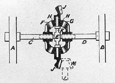
The principle illustrated by this diagram may now be followed in fig. 4, which illustrates a common form of live axle
Fig. 3. Diagram to illustrate Differential Action
driven by a horizontal jointed rod from the motor and a bevel pinion. The functions performed by the parts are the same as those having the same letters in fig. 3.
The differential gear consists of two bevel wheels f and g, each tooth of which acts in the same way as the arms f and g of fig. 3, and two or more bevel pinions h each of which acts in the same way as the cross-piece h in fig. 3, but by means of its teeth bearing upon the teeth f and g of the bevel wheels instead of the one tooth or arm f or g in fig. 3. These bevel pinions are loose upon the pins on the end of the piece k, just as the piece h is loose on the pin k in fig. 3, but instead of the pin k being pulled by a rod it is carried round by the bevel wheel j, acting in the same way but relatively instead of through a horizontal line of short range. If now the resistance to the wheels a and b be the same, the pinion h (acting in precisely the same way as the cross-piece h of fig. 3) will by its teeth at f and g impart equal degree of rotation to both, but if wheel b be on the inner side of a curve or meets with obstruction greater than that to a, then the pinion h will turn on its pin k, and allow one wheel to move faster than the other. That is say, the pinion h will impart the same push to either wheel a, b, and if one of these moves more easily than the other from any cause, it accommo-
Fig. 4—A Differential Gear
dates that wheel by itself turning and allowing the wheel to move more rapidly than the other. This accommodating action of the gear is important for free turning of corners, but it has its disadvantage, in that if one wheel, while the vehicle is on the straight, meets with more obstruction than the other, the gear allows it to be obstructed, and tends to push the other wheel round against the action of the steering gear. Correspondingly, if one wheel is on a greater thickness of greasy mud or a more slimy bit than the other wheel, it has more freedom of, and help to, rotation than the other, and skidding or sideslipping on the greasy road results and is aggravated. Hence in the heavy steam lorries, means are provided for throwing the differential gear out of action.
On many cars the bevel wheels of differential gear were too small in diameter, and hence there was insufficient room to get in pins of sufficient size to carry the pinions h, and rapid wear and breakage took place. In any case it is necessary to have ample diameter for these parts, and to see that they are kept well oiled, not only at the pins and gear teeth but at the centre of the axle, where the two parts are joined by means which allow them to rotate differentially on a centre pin and in the bearings in the differential gear-box which surrounds the wheel j. This box is not shown in the diagram, fig 4. The dotted lines at m indicate the bevel pinion on the spindle l., which is driven through a jointed rod by the motor. The means of transmission of the power to this spindle have been described in other chapters. The automobilist should occasionally jack up the rear of the car so that both drivers are free of the ground, so as to see that the wheels run equally free when either wheel is held, thus testing the free working of the differential gear, finding slack if it exists, and testing generally the condition of the gear and connections.
Steering Gear.—The loss of a ship's rudder is a small loss comparatively with that of the breakage or carrying away of an essential part of the steering gear of a motor carriage, especially of a high-speed car. The ship will continue to float and in most cases the stopping of the engines removes immediate danger from collision. With a broken steering arm or connecting-rod a car with its occupants may be hurled into a ditch, or ravine, or river before the driver has realised what has happened, and long before the brakes could do any good. The first provision against the helplessness that must, and the disaster that probably would, follow broken or disconnected steering gear, is sufficient strength in the parts. It should be as direct and simple in arrangement as possible, because least liable to disarrangement and because gear with chains and short rods and connections through springs have so many more points for possible looseness and losses and more to examine and yet be uncertain about. A few pounds in weight will make all the difference between weak and bending untrustworthy parts, and certainty, so far as strength will give it. The second means of providing against accident is frequent minute inspection of every connection, tightening of nuts, renewal of worn pins, assurance that pins cannot leave their place or split pins be lost, and careful oiling and covering of joints so as to prevent ingress of grit and reduce wear as much as possible.
The choice between locked steering gear and what is commonly called direct steering gear is very much a matter of personal choice. The locked gear generally acts through a worm and wheel or quadrant, and remains where it is set by the driver. The free or direct gear moves with the impulse or pressure brought against the steering wheels or one of them by any ruts or obstructions on the road. This movement has to be resisted by the hand of the driver, as it is in some of the steam-cars with lever-steering handle and many of the wheel-steering light cars. An objection to the locked steering gear is that the worm gear rigidly holds the whole of the connections between it and the steering axle. Hence any shock by blow or heavy push at one wheel has to be withstood in all its force by the steering connections. The lever or free gear on the other hand is not rigid. It is accommodating, and the shock on the steering parts is very much lessened, and in many cases eliminated, by very small movement of the steering lever or wheel. The objection to this is that the hand has to accommodate itself to and permit this movement and still preserve the steerage control. If it be resisted the hand and arm feel in a very disagreeable way the effects of the shocks, especially at high speeds on bad roads, and of which the steering gear is relieved. The driver, however, soon learns to keep a loose but ready hand on the steering wheel or lever just as in riding a bicycle or tricycle. On very light and moderate speed cars lever or free-wheel steering gear would seem to be in every way sufficient and quicker in action than the locked gear, and while running on good smooth roads there is very little tendency for the steering wheels to wander one way or the other.
For the heavier and higher speed cars the locked steering will probably continue to be preferred, the steering connections being relieved to some extent of the severity of shocks by the interposition of spring buffers in the rod ends, thus securing the advantage of fixity of position of wheels and direction of running under any circumstances. It may be remembered, however, that with the long wheel-base of the passenger brakes run by the Lifu Company two or three years ago, the lever-steering worked with great ease at thirty-five miles per hour, but the axles of the wheels were inclined so that the point of incidence of the wheels on the road was directly under the steering-axle pin, and hence most of the shocks were delivered to the axle and not to the steering gear.
The automobilist should frequently jack up the front of his car so that the front wheels are free of the ground. Then he can test the condition of all the steering-gear parts between axle-arm and steering pillar, and see and feel every joint and find out where, if any, and how much looseness or wear there is in any part. He cannot do this properly while the weight is on the wheels. Looseness between steering wheel and end of steering pillar can be found at any time. He should never allow 'hurdle fitters' or 'horseshoe fitters' to attempt to refit of alter any part of his steering or other gear, any more than he would allow a 'hedge carpenter' to alter or repair the body of his car or the Chippendale chairs in his drawing-room. Only good experienced workmen, and above all trustworthy workmen, should be allowed to do this work. The refitting of steering worm and quadrant or of the nut on steering screw, when that form is used, must be done by a good fitter, unless the double nut, with one half adjustable independently of the other, is used.
Brakes.—Next to trustworthiness in axles, wheels, and steering gear the sufficiency and certainty of action of the brakes are of the utmost importance. So long as the axles do not break and the steering gear steers, an expert driver can rub along with very poor brakes until familiarity with risks and dangers leads him into a smash, or until some very near squeak makes him shudder when he thinks about it after he is in bed and the light out; and then he looks to it on the morrow. Of these incidents we do not hear much, but we all know of the smashes and the fatal accidents that have happened to those on runaway or brake-given-way cars, and Mr. Hutton's narrow escape at the end of an unwonted rush downhill into Grantham, and Mr. Graham White's run-away at Dover, are instances of the more obvious kind of evidence of the necessity for good brakes. For the beginner there is no working part of a car so necessary to his safety as the brakes. He finds that stopping is very frequently more important than going if he values either his life or that of others, or wants to save his car and is not anxious to pay for smashing carriages or horses. Even the makers of the lighter French vehicles no longer fit their cars with brakes not big enough for a bicycle or good enough for a horse-rake.
Many brakes have in the past been generally made or fitted so that they will only hold a little in any direction, some that would only hold well in one direction, and some that held too well, came into action too severely, in one direction, namely forward, and very few that held well in the backward direction. A great deal of attention has lately been paid to this question, with the result that brakes long well known to mechanical engineers have been applied to motor vehicles.
A common form of brake that will hold only in one direction is shown in diagram fig. 5. In this a brake drum a is surrounded by a brake band b, fastened at one end to a fixed stud at c, and pulled at the other end d by a rod f, connected to a pedal e. This brake acts perfectly so long as the drum a rotates in the direction shown by the arrow, because the friction of the band on the drum from near c to d pulls on the band in the same direction as the pedal, and thus the greater the pull at d the greater the frictional grip round to d. As soon, however, as the car is reversed or moves backward, so that the drum turns in the opposite direction, the friction of the band upon the drum pulls the band round towards the fixed point e and further frictional grip does not take place, as the tendency is to reduce the pull on c. If now the band be coupled at c
Fig. 5—Brake which holds in one direction
to a lever pivoted at h, as in fig. 6, the other end being coupled to the end d of the same lever and pulled by the rod f and pedal e, the brake will act both ways. If the drum be turned in the backward direction of the arrow, the pull at d will not be lost through the effect of the fixity of the point c, for both ends
Fig. 6—Brake which holds in both directions
c and d are pulling on the drum and increasing the pull on fincreases the frictional hold in a rapid degree.
A good form of brake is that shown by fig. 7, in which the pull on the rod f from pedal e pulls the arm d, and thereby pushes the links c outwards and forces the blocks b outwards into the brake drum ring a, the whole of the brake tackle shown being prevented from rotation by the radius rod c, attached to the frame. It will be seen that this brake holds equally well in either direction. It is made by Messrs. James and Brown.
Other forms of brakes which act in both directions have been adopted, as in the Cannstadt-Daimler cars, the Riker, the Panhard Krebs car, the Electric Vehicle Co. and others, and more recently by Darracq, De Dion, Bouton, and Decauville, but many are still fitted of the untrustworthy kind. These are types, and all but the substantially made and well connected brakes should be avoided.
Brake bands with wood blocks attached will work very well, but well-fitted bands with metal-wearing surfaces are much
Fig. 5—Brake which holds in both directions
better, and brakes made up of small wire ropes and tacked or tied on or threaded wood blocks are not to be encouraged.
However good the brake, it needs careful inspection and occasional adjustment, and much more thought than is usually bestowed on so important a factor of safety.
A fruitful cause of accident and of wear and tear of brakes, tyres and car generally, is the abuse of a good firm-holding brake. Maintaining high speed to the last moment and depending on sudden application of the brakes is a very bad and often dangerous practice.
The injudicious use of brakes or the rash driving which entails the excessive employment and the abuse of brake power, is not only to be condemned because it is so likely to cause the breakage of the brake gear, and so render a driver absolutely helpless, but because it is one of the fruitful causes of rapid tyre wear.
When a car weighing with its passengers one ton is stopped from a speed of 20 miles an hour in a length of say 15 yards, the accumulated energy in the mass in motion is about 13 tons, and this is dissipated by work done on the tyres. It is remarkable that even the best of tyres stand this enormous strain as they do. At 20 miles per hour the car travels 45 feet in the time taken to stop it, but the Automobile Club trials of January 1902 show that the distance in an assumed emergency stop may be much shorter than this, and it will not be an exaggeration to assume that the car may be stopped in 35 feet or in from 21/2 to 3 seconds; and in this space the wheels will have made only from four to five revolutions, according to their diameter.
The whole, then, of the work, equal to that of raising a ton 13 feet high, is done by the tyre surfaces in four or five turns, or less than three seconds. This statement is sufficient to enable even those who have the very least acquaintance with mechanical matters to appreciate the danger and the costliness of the injudicious driving that leads to the abuse of the brakes. It may be desirable to record here that the Automobile Club brake trials above referred to showed that on a flat and nearly dry good road a car could be stopped at the speeds and in the car lengths given below:—
From 11 to 14 miles per hour in 14/5 car length.
From 15 to 17 miles per hour in 2 car lengths.
From 18 to 20 miles per hour in 23/4 car lengths.
From 20 to 24 miles per hour in 31/2 car lengths.
Wheels.—For voiturettes there does not appear to be any structural superiority in wood wheels, making them in this respect preferable to well-made and well-proportioned wheels of the cycle type. They are a little more easily cleaned, and are, perhaps, neater in appearance; but even this is doubtful in very light cars. For the heavier cars the wood wheels of the Hancock type are preferable because of their combined strength and resilience, as well as for advantages as to cleaning and appearance.
There are, however, no points in particular that the beginner has to consider except to beware of wheels made with very light spokes and felloes. Look well to the joints in the felloes and every joint of every adjoining spoke in the bosses. Well-made wheels show no movement at these points after hundreds of miles of running. For the most part the buyer must rest upon the honesty and reputation of the maker, but he may help the longevity of the wheels by judicious and gradual use of clutch and brakes, and by guarding against loose or lost nuts on the wheel boss flanges or slackness on the axles. Any slackness of the rim on the felloes should be attended to by a wheelwright. The cycle wheels of the light voiturette seldom require attention except in case of accident, and they may generally be entrusted to any of the accredited repairing shops.
As a rule it may be taken that the larger the wheel the smoother the running of the car. Very small wheels are to be deprecated on this ground, and also because the severity of the shocks to the whole car increases very rapidly on bad roads with decrease in diameter of wheel, for reasons which have been given in the book already mentioned.
All the wheels should be of the same size, because the same tyre will then fit any wheel, and half the number of spare-covers and inner tubes are required as compared with the requirements when the wheels are of different sizes.
The appearance of a car with wheels of equal size is moreover better than when the steering wheels are smaller, and except that custom, dictated by the old locking plate and centre pivoted axle, required the small wheels in front, there is not only no reason for small steering wheels in motor carriages, but if any difference is made they should be larger than is necessary for the driving wheels.
 Arabic
 English
 Deutsch
 French
 Italian
 Español
 Català
 Português
 Nederlands
 日本語 Japanese
 Polski
 Russian
 Svenska
 Ukrainian
 Türkçe
 Bahasa Indonesia
 Bahasa Melayu
 ไทย Thailand
 Filipino
 हिन्दी Hindi
 বাংলা Bengal
 اردو Urdu
 Tiếng Việt
 한국어 Korean
 粵語 Cantonese
 繁體字 Taiwan
 中文 Chinese
 閩南語 Bân-lâm-gú
 Bulgarian
 Čeština
 Dansk
Dansk Esperanto
 Euskara
 فارسی Persian
 עברית Hebrew
 Magyar
 Norsk Bokmål
 Română
 Latviešu
 Lietuvių


_0219.jpg)
_0220.jpg)
_0221.jpg)
_0222a.jpg)
_0222b.jpg)
_0223a.jpg)
_0223b.jpg)
_0224.jpg)
_0226.jpg)
_0227.jpg)
_0228a.jpg)
_0228b.jpg)
_0231.jpg)
_0233.jpg)
_0234.jpg)
_0235.jpg)
_0239.jpg)
_0245.jpg)
_0248.jpg)
_0249.jpg)
_0254a.jpg)
_0254b.jpg)
_0255.jpg)